TruckIRS Installation (1973-79 Ford)
Ford Trucks manufactured between 1948 and 1972 had rear frame rails that run parallel and measure 34″ (outside to outside). Chevy Trucks manufactured between 1955 an 1959 also measure 34″.
Ford Trucks manufactured between 1973 and 1979 frame rail measure 38″ (outside to outside). With this in mind, the TruckIRS kits are designed to specifically fit those two different era Ford Trucks. The instructions below illustrate the differences for installing the TruckIRS kit in 1973-79 Ford trucks.
This page shows the specific instructions for installing a Thunderbird IRS or Lincoln Mark 8 IRS in a 1973-1979 Ford pickup… some refer to this series as the Dentside. As it relates to the installation of an IRS subframe, the rear frame is wider on the dentsides than earlier Ford pickups. The earlier trucks had an outside / outside dimension of 34″. The dentside measures 38″ outside / outside.
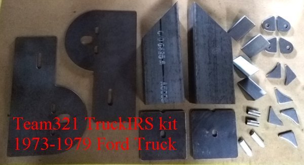
The rear mounting brackets provided in the truckIRS kit are the same. The hardware package includes some slightly different gussets and the forward mount is also different.
Here is an image showing the contents of the TruckIRS kit for 1973-79 Ford trucks – and others with 38″ frame rails.
It is assumed that those looking to install a truckIRS kit in a dentside are already familiar with the installation procedure for installing a truckIRS kit in an earlier Ford truck.
Be sure to view this installation sequence first before reading any further.
This installation sequence below is meant as a means of pointing out the differences.
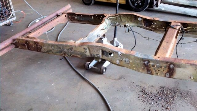
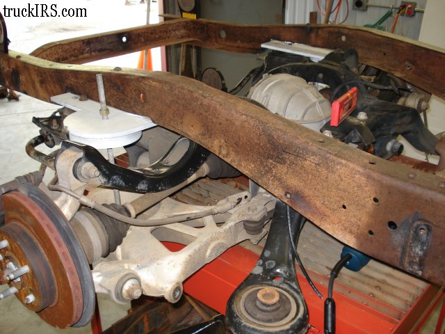
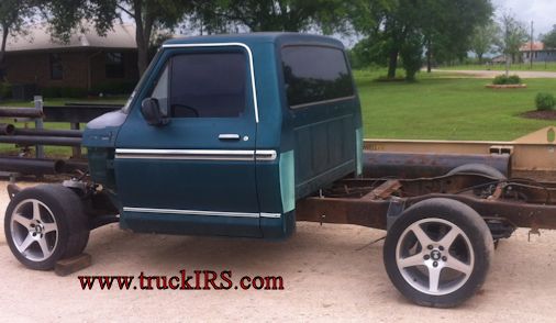
We begin the install with a bare frame from a 1979 Ford truck, the rear axle was removed and all exhaust, brake lines, etc. moved out of the way.
During the truckIRS installation, I used a white painted right side (passenger’s side) rear mounting bracket to make it easier for the viewer to tell which side I was working on. I tried to show both sides of the install, but in some cases I only show the right or the left.
The long horizontal line and tick marks were used to create a 3D model of the truck’s frame as shown here.
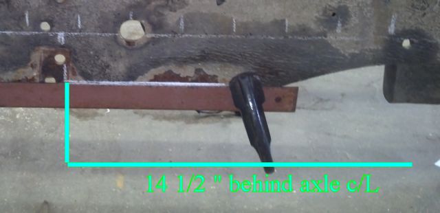
Here is a view from the passenger’s side showing the location of the horizontal cut to level the bottom of the truck frame to accept the IRS subframe.
Notice the bump stop at the lower right corner of the image. This was used to establish the axle center line.
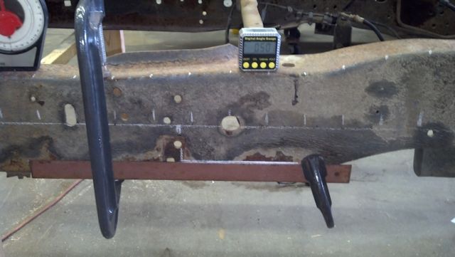
The vertical line and subsequent cut, measure 14 1/2″ behind the axle centerline. Make sure to use a level and a steel straight edge to draw this line. Clamp the steel straight edge in place along the side of the truck’s frame to be assured of a straight cut.
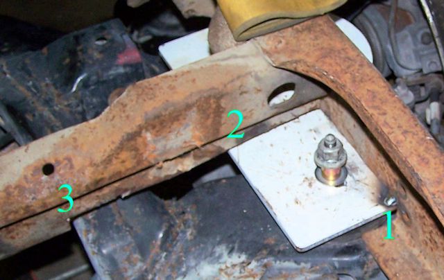
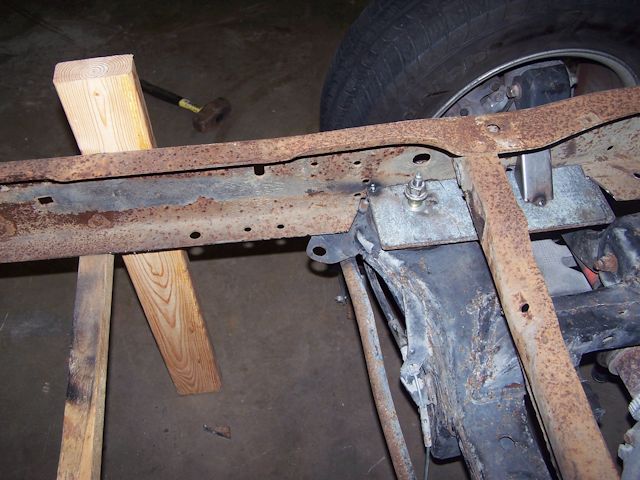
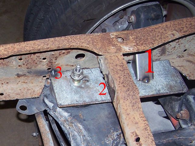
I’m skipping ahead to show three areas of interference when making the cuts in the truck’s frame. Regarding the image below:
#1 shows an area of the frame that was cut to clear the rear mount, but the IRS subframe itself interferes with the frame. So an additional cut must be made to the frame to accommodate. (I show this later in the instructions).
#2 shows the original crossmember that can be retained, but must be cut for the rear mount to clear.
#3 shows how the cut in the crossmember shown in #2 must be continued inward toward the center of the truck’s frame to clear the IRS subframe.
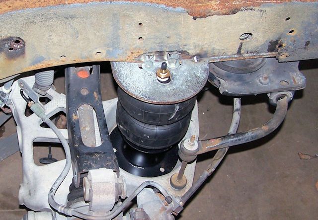
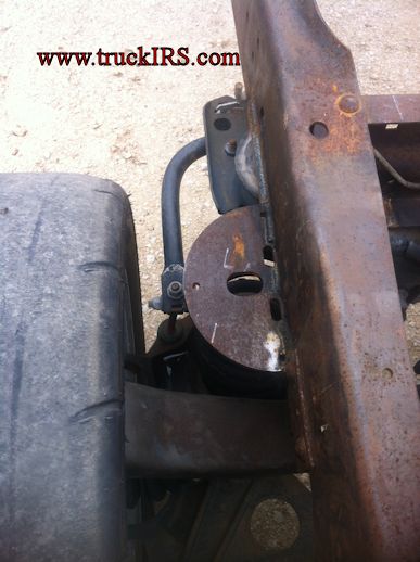
Another clearance issue I discovered – that I want to point out asap – is access to the 3/8″ bolts that position the airbags. If you are installing coil springs, this does not apply. Here is the before / after.
BEFORE
![]()
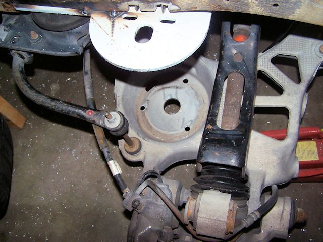
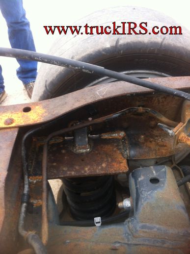
AFTER
![]()
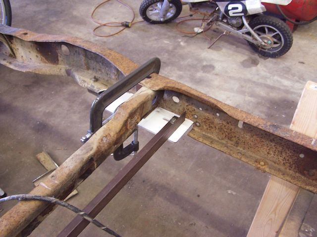
I wanted to show an alternate way of located the rear mounts for welding to the truck’s frame. You can either roll the entire subfame under the truck’s frame to position the rear mounts for welding….
Or this alternate method… I used a piece of angle with 12mm holes drilled the same distance apart as the IRS subframe – 34 5/8″ inches on center.
I positioned the left and right rear mounts in place with angles and brackets – checking alignment twice, three times… etc.
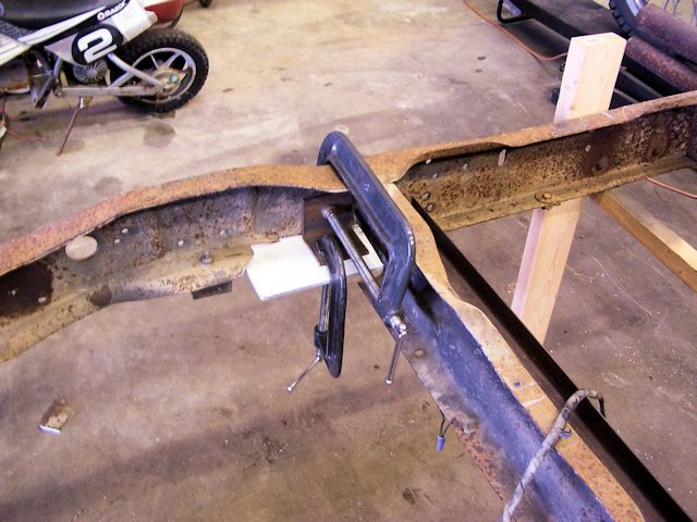
When I was happy with the placement… I placed a few tack welds to attach the passenger’s side rear mounts to the truck’s frame.
and the same for the driver’s side…
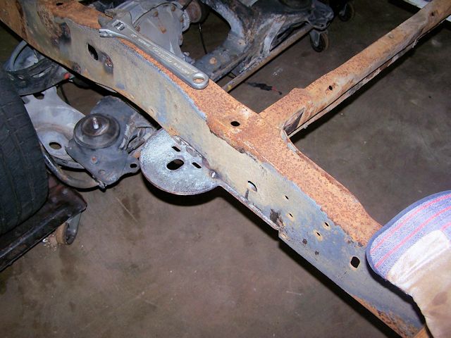
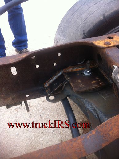
Now you can roll the IRS subframe into position and bolt it to the rear mounts. Remember your rear mounts are only tack welded in place and cannot support the load of the IRS subframe. Be sure to lower the frame rails to the subframe to check everything. Notice the corner gusset are shown welded between the rear mount and the inside of the frame rail – just ahead of the original crossmember.
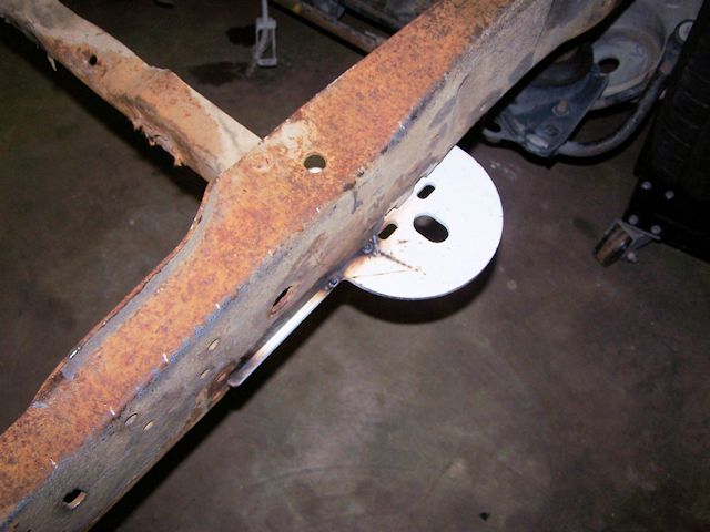
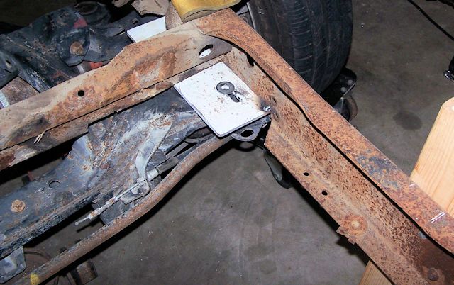
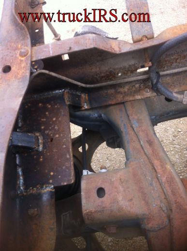
Here is a shot of the driver’s side… the black arrow indicates the area of interference that must be removed… as stated earlier.
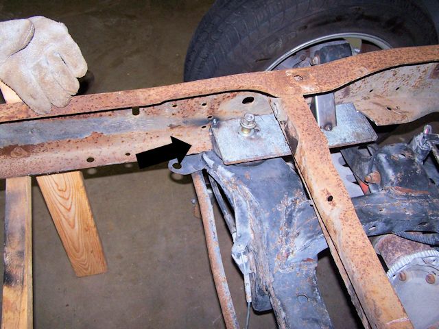
…. and here is an image with the small piece of frame removed to clear the rear part of the IRS subframe behind the mounting bolt.
You need to clearance the driver’s side as well as passenger’s side.
I’ve tried a variety of approaches to install the air springs, and the easiest approach is to remove the bolt connecting the upper control arm to the spindle.
Assemble the airspring and mounting base (available from Team321 for $15 / pair) and install the assembly into the lower control arm bucket.
(you will need to remove the 3/8″ bolts from the top of the airbag).
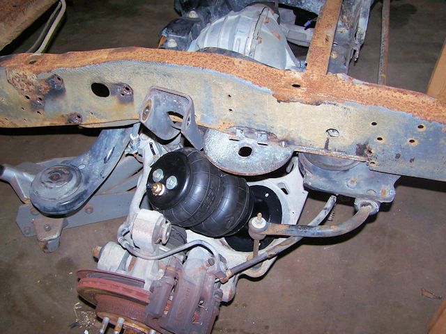
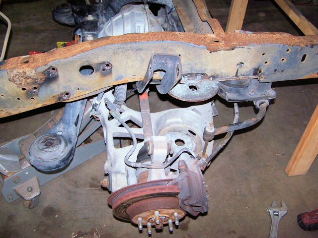
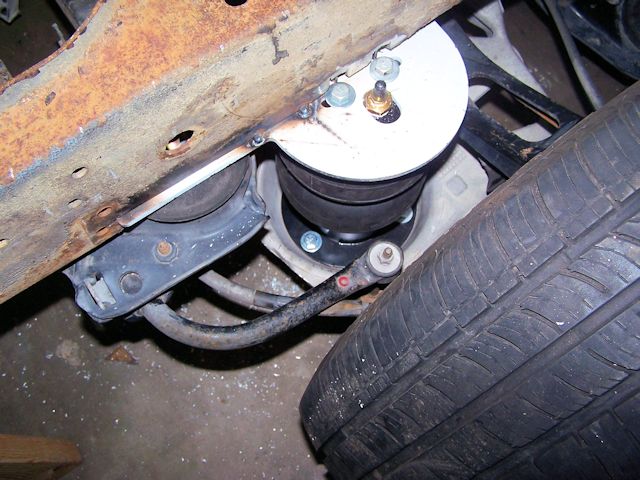
With the airbag assembly in place, you will notice the three holes in the base of the airbag pedestal.
Moving over the passenger’s side… notice the three holes in the lower control arm.
I marked these holes with a black sharpie, removed the airspring assembly, drilled 3 holes in the lower control arm bucket…
re-installed the airspring assembly and installed the 3/8″ bolts to hold the base to the lower control arm.
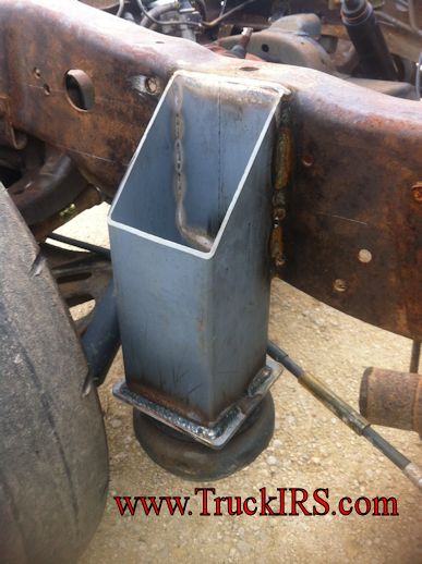
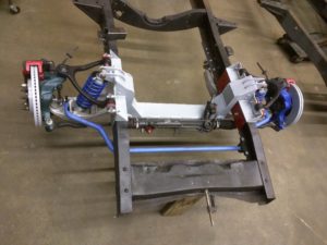
The rear mounts are welded in place… time to address the front mounts. Like before, make sure that the IRS assembly is level.
Using a floor jack under the forward mount, raise the forward mount into position and bolt the forward truckIRS mount to the IRS subframe.
#1 gusset is positioned properly.
#2 (gusset – similar to gusset #1- not shown) but will be positioned to tie the rear P shaped plate the truck’s original crossmember
#3 will be a 1/4″ thick triangular gusset similar to those used in the original truckIRS installation.
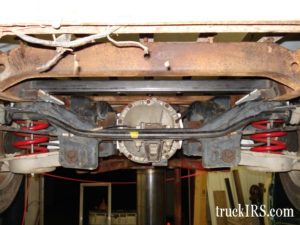
Here are a few customer-provided images showing rear mount gusseting. Once this portion of the install was complete and photographed, the IRS subframe was removed and the frame and truckIRS mounts were sandblasted and coated prior to reassembly.
Here is an image showing the contents of the TruckIRS kit for 1973-79 Ford trucks – and others with 38″ frame rails.
For more information…Call (321)960-5945 or email dave@team321.com
Front Suspension
Rear Suspension
Team321 Customer Map