
Crown Vic Installation Kit
Installation Sequence for Crown Vic Kit in a 1965 – 79 Ford truck
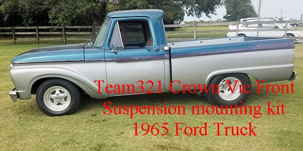
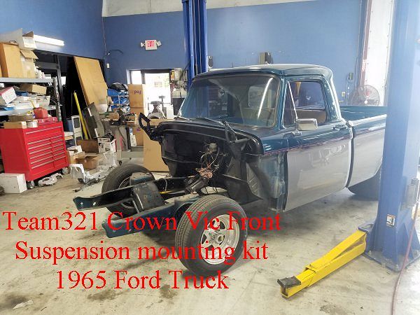
1965 Ford Truck
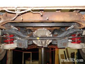
Here is a typical Crown Vic crossmember (2003 – 2011) available almost anywhere… They were installed in Ford Crown Victoria, Mercury Marquis and Lincoln Towncars.
After a significant amount of cleanup.
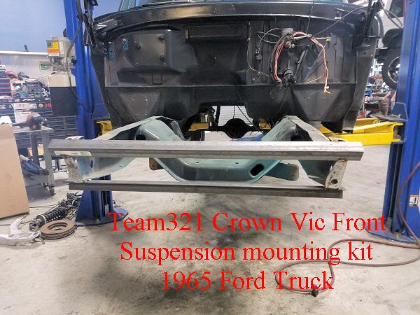
One of the more difficult parts of the installation is the removal of the Factory Ford steel crossmember. It is highly recommended to weld steel bars on the front of the crossmember (left to right) to keep the frame rails from moving during demo and installation.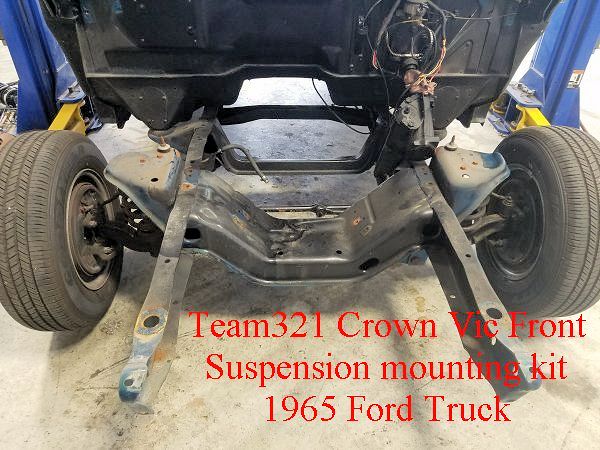
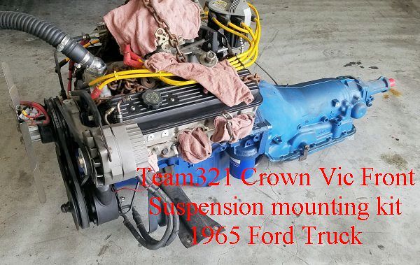
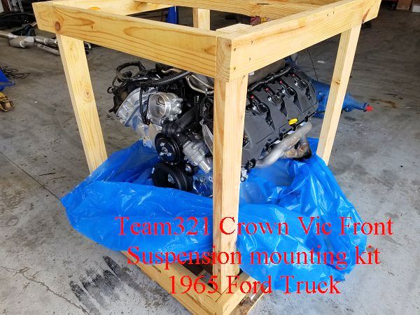
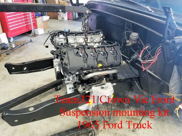
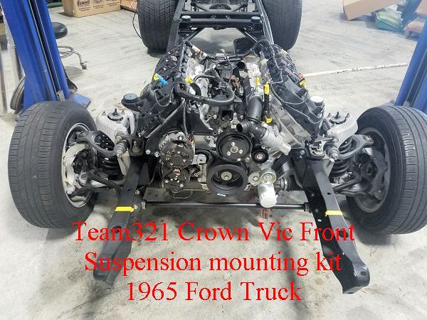
This is the engine / trans combo that was installed in the truck prior to the swap.
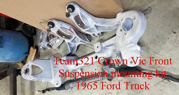
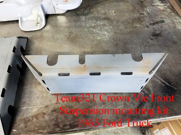
Team321 Crown Vic Installation Kit contents for 1965 – 79 Ford trucks.
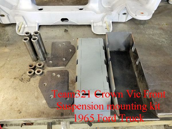
Another view of the Bent Boxing bracket (one per side). These boxing brackets stiffen the frame rails and easily locate the the holes and crush tubes to mount the factor crossmember.
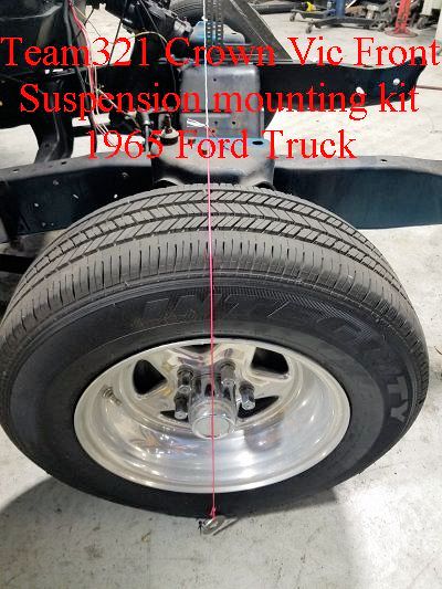
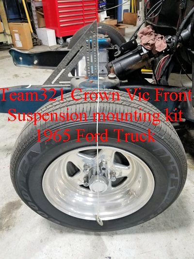
Always a good idea to mark your axle centerline prior to removing the factory crossmember and suspension components.
There are more rivets than I care to count, but one by one, you must remove them to free the frame rails of all the shackle mounts, shock mounts and other brackets.
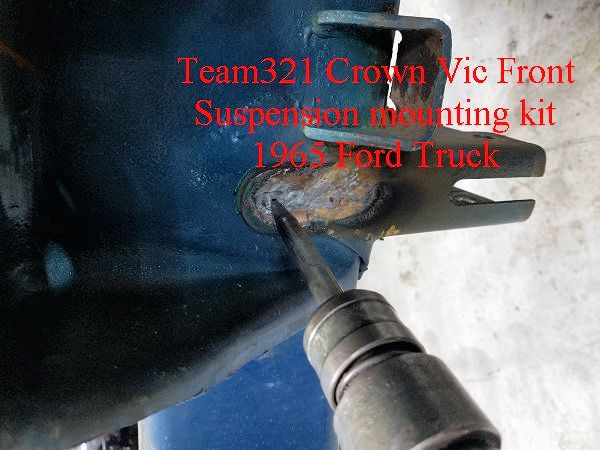
As mentioned earlier… brace the frame rails prior to removing the factory crossmember.
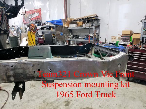
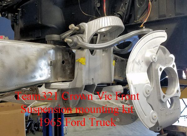
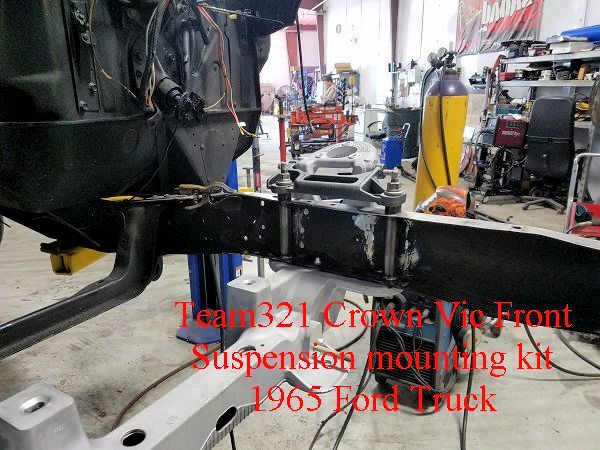
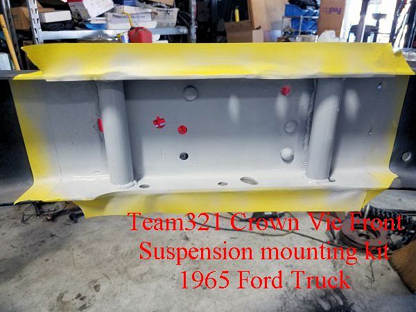
Initial fitment of crossmember
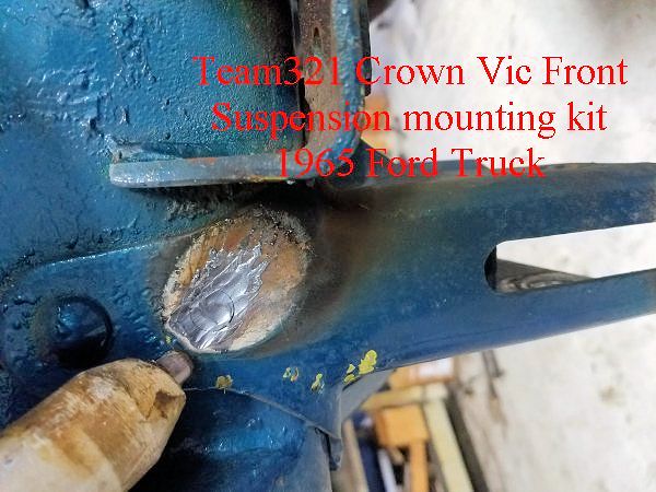
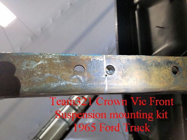
After marking the axle centerline, the alignment pin hole is marked. It is very close to one of Ford’s original bump stop bracket mounting holes.
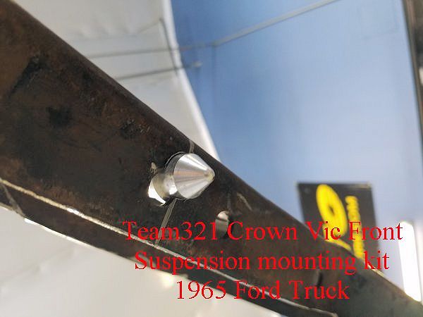
Alignment pin through newly drilled hole in the frame.
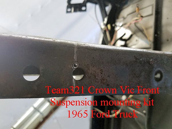
Holes for mounting bolts and axle centerline indicated on frame rail
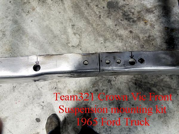
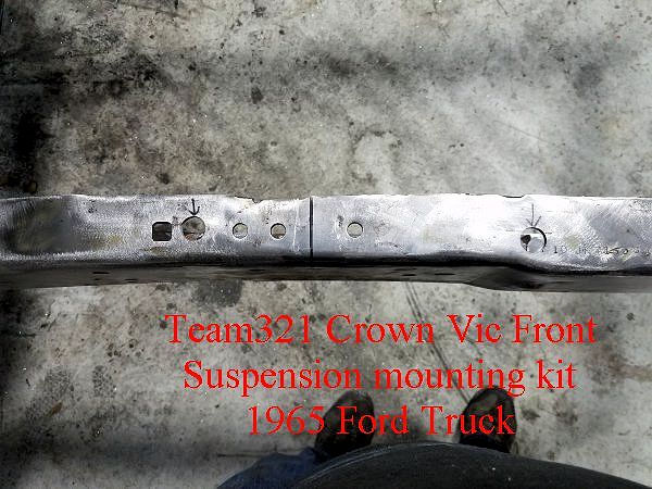
Note the alignment pin hole in the bottom of the frame rail.
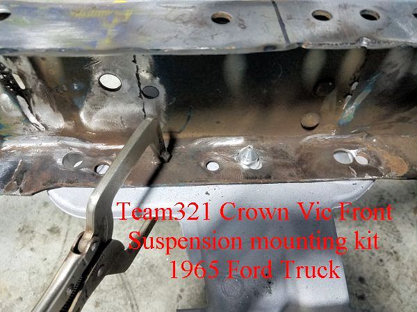
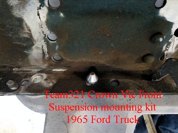
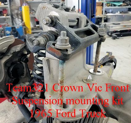
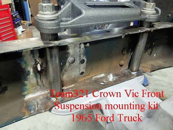
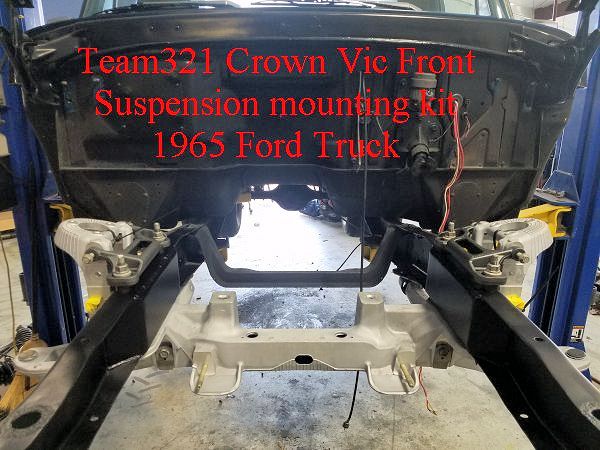
Crush tubes and spacers in place… Crossmember bolted in place to verify fit.
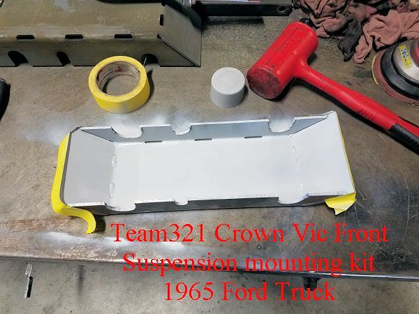
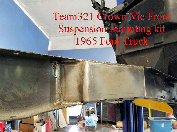
Bent Boxing brackets are coated prior to install
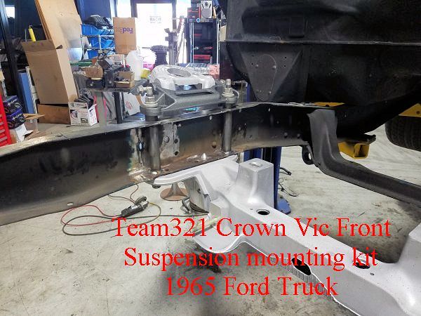
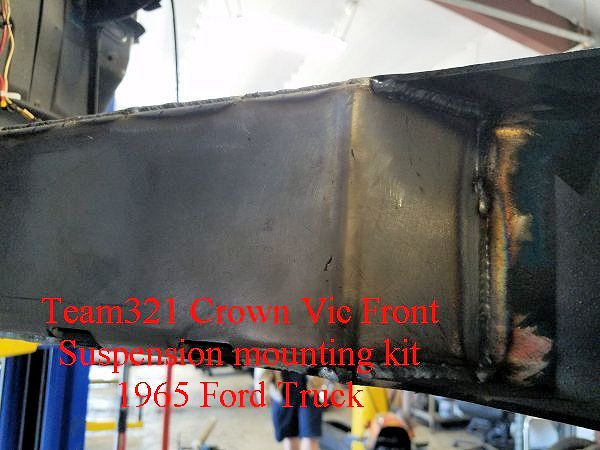
Bent Boxing brackets are welded into place.
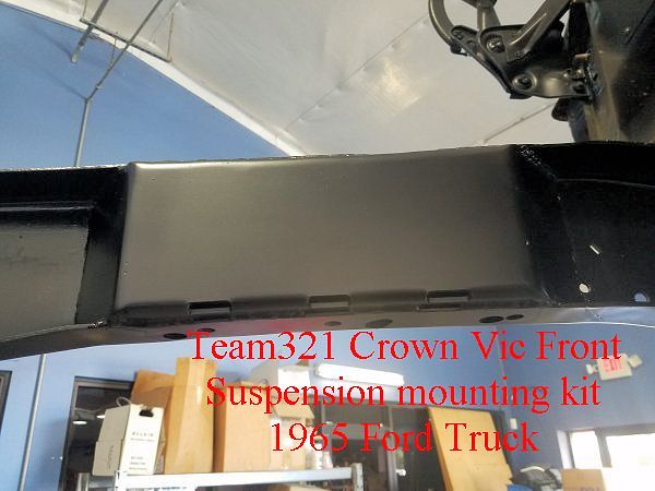
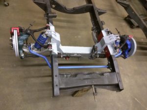
Very clean installation!
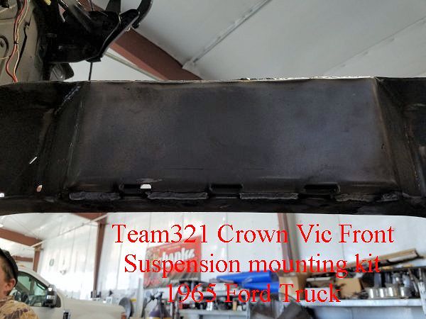
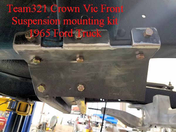
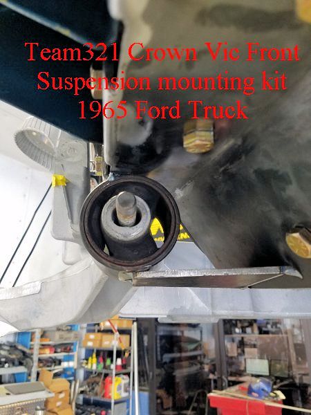
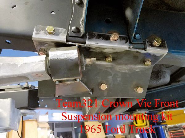
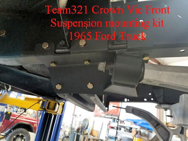
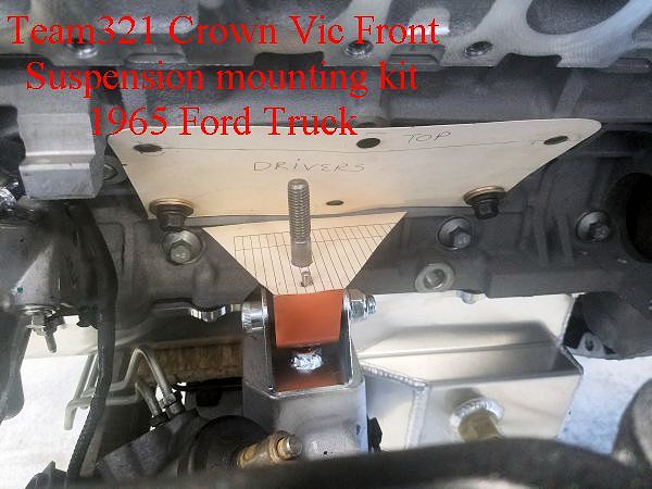
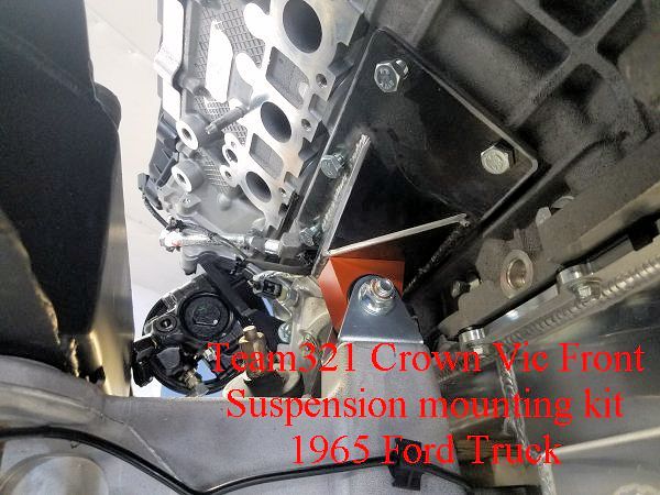
Outside View of the Trailing Arm mounting plate.
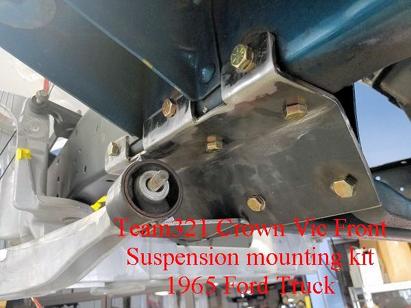
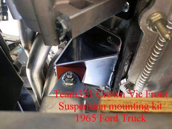
Inside view of the Trailing Arm mounting plate.
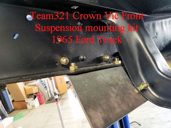
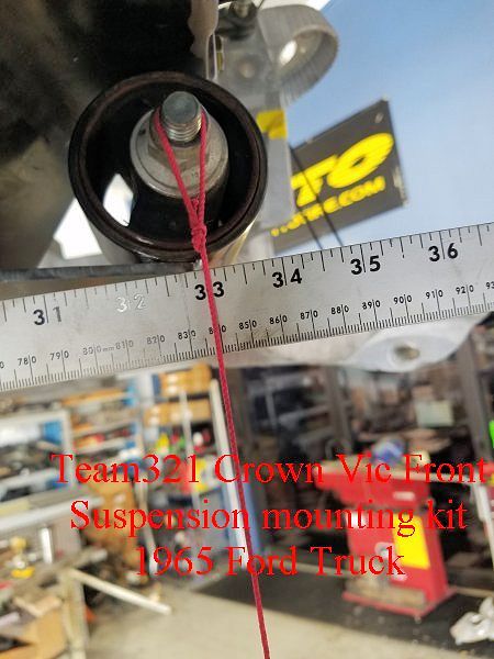
Illustration showing the separation distance from stud to stud of the lower control control arm trailing arm mount.
Note the orientation of the Oval slot around the stud… this must be positioned so the flat spot of the ovals are parallel to ground.
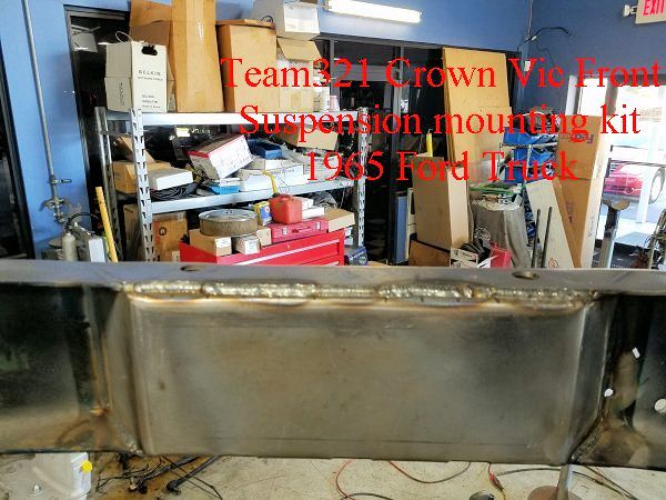
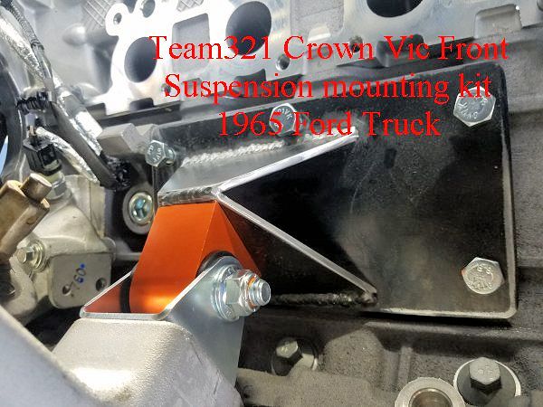
The bushing housing is spot-welded to the bracket prior to final welding.
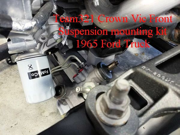
Motor mounted into place.
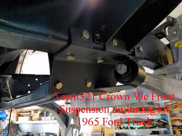
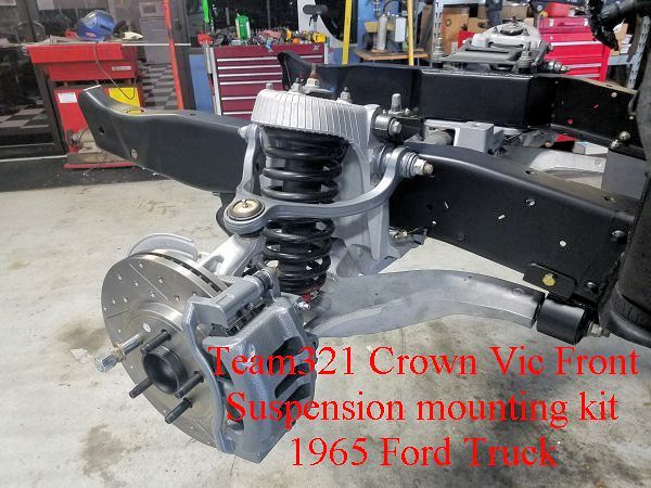
Lower control arm mount after final welding and paint.
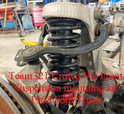
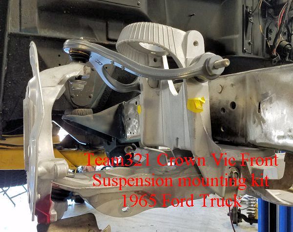
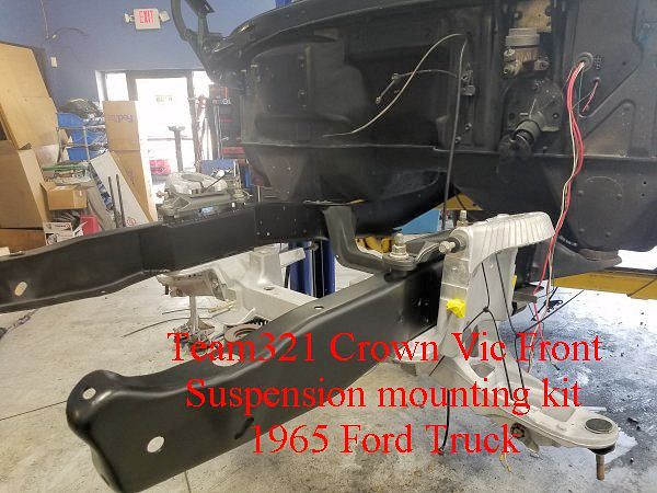
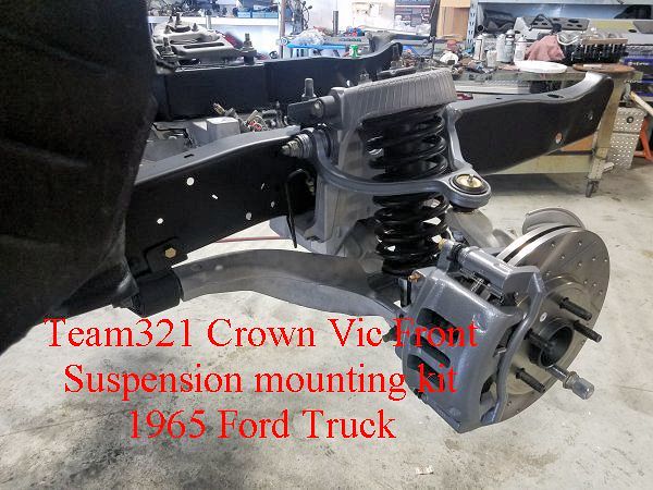
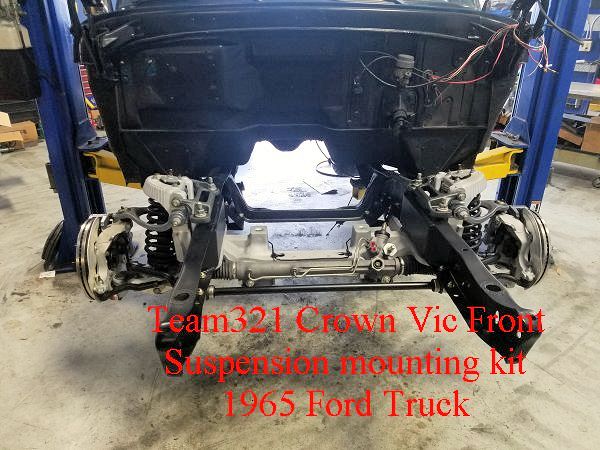
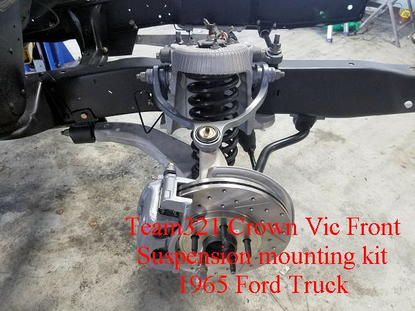
Passenger’s side Suspension and Brake components installed.
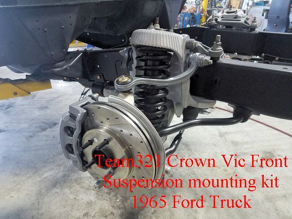
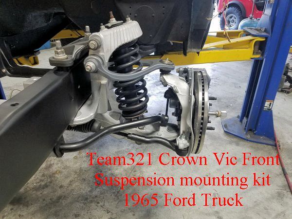
… and driver’s side installed.
![]()
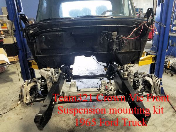
Installation Complete!
For more information…Call (321)960-5945 or email dave@team321.com
Front Suspension
Rear Suspension
Team321 Customer Map