Front view of a Ford Mod motor engine block and passenger’s side head.
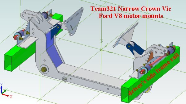
Here is a better detailed view of 3D CAD image showing the motor mount components. The associated hardware will be provided as well… but for the sake of showing how it all fits together, the hardware was hidden from the image. Having accurate CAD models makes for easy modifications to the mounts. These mods (like moving the lcoation of the engine up or down or left or right) are available at no charge…
The image below shows the contents of the (Mod Motors) 4.6L, 5.4L and Coyote V8s.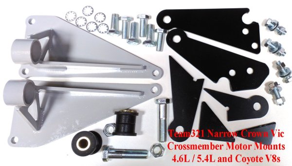
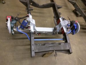
Team321’s goal is to provide a variety of motor mounts that can be interchanged and easily installed on the Narrow CV crossmember.
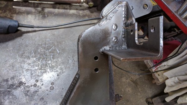
Installing the motor mounts is straightforward… Every crossmember includes 4 pairs of 3/8″ diameter locating holes. These holes provide the locating points for the motor mounts. These 3/8″ holes are drilled in both the forward plate and the rear plate – on both the drivers’s and passenger’s side. This allows for options in positioning the engine. The brackets that mount on the engine can also be mounted in either orientation. These combinations of mounting positions allow you to choose how far forward or rearward to mount your engine.
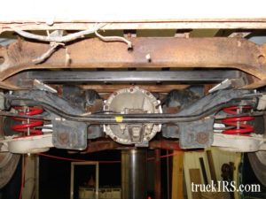
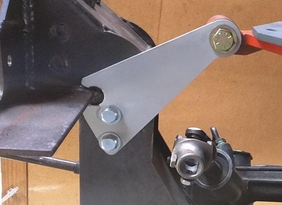
The photos in this install sequence show the 3/8″ holes drilled in the rear plates.
Generally, motor mounts consist of a bracket that mounts to the engine block, some type of bushing and plates permanently affixed to the crossmember or truck’s frame.
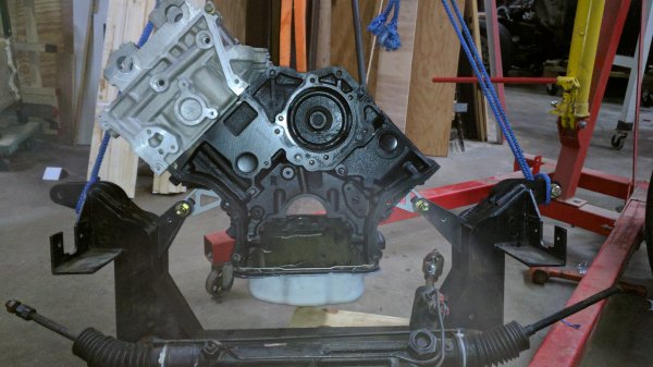
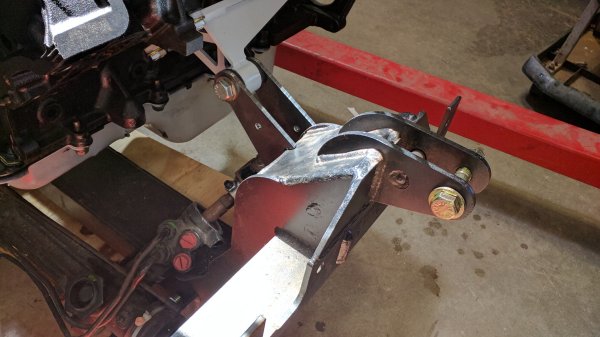
Team321 has test fit these engines with rear sump oil pan. I’m waiting on the arrival of exhaust manifolds to further validate the fitment. Here are a few images of the driver’s side.
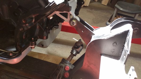
The 3/8″ holes you drilled through the crossmember plates positively locate the motor mounts… insert the provided 3/8″ mounting hardware to locate the motor mount plate.
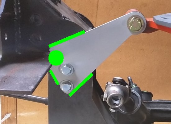
Once you have the driver’s and passenger’s side mounts properly positioned and you’re happy with the engine’s fore / aft position on the crossmember, weld the plate to the crossmember – as indicated by the green overlay… once welded the 3/8″ hardware can be removed and the holes plug welded.
This image of the CAD drawing shows a triangular gusset (included) that is positioned on either side to strengthen the mount. At the time of test fitting I failed to photo these triangular gussets, but show them here in the CAD drawing indicated by the red arrows.
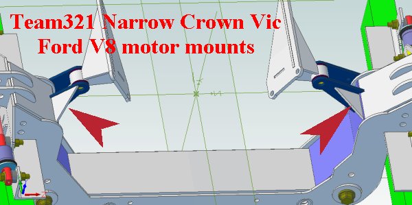
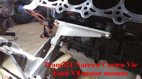
The image below shows the passenger’s side… note the brackets and triangular gussets are smaller on the passenger’s side vs. the brackets used on the driver’s side… this is due to the offset of the engine toward the passenger’s side.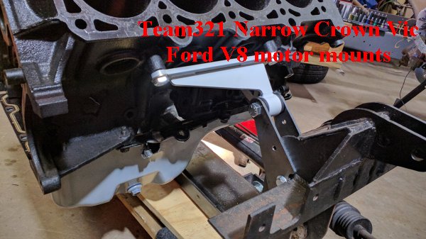
For more information…Call (321)960-5945 or email dave@team321.com
CLICK HERE for more info on Motor Mounts
CLICK HERE to see additional Narrow Crown Vic crossmember-related information
![]() Back to Team321 Homepage
Back to Team321 Homepage