TruckIRS Installation
Instructions for installing a Thunderbird IRS or Lincoln Mark 8 IRS in a classic Ford pickup.
Click here to download a printer friendly PDF file with the details.
The installation sequence below if for 1948 – 1972 Ford Trucks and 1955 – 1959 Chevy Trucks and all other trucks with outside / outside frame rails separation of 34″
Click here for the installation differences for 1973 – 1979 Ford Trucks.
A Ford in a Ford… no, we’re not talking about a small block or a big block, we’re talking about your Classic Ford truck’s rear suspension. Ford made plenty of Thunderbirds, Mecury Cougars and Lincoln Mark 8’s from 1989 through 1998 leaving us with a great supply of Independent Rear Suspensions. These cars came equipped with V8 Engines, rear disk brakes and the ever-popular 8.8 rear differential. The IRS assembly from these vehicles is attached to the unibody via 4 12mm bolts – making the IRS relatively easy to remove from the donor vehicle.
The only remaining question is – How does the IRS assembly attach to the Ford Truck frame? Team321 LLC of Cocoa Beach, Florida manufactures adapter brackets that allow you to bolt the complete IRS assembly to the Ford Truck Frame. The following images show the necessary modifications to the truck’s frame, the installation of the IRS adapter brackets, the installation of the IRS assembly and finally a view of the truck’s ride height with the bed installed. For photographic reasons, the adapters were painted white. There are four adapters – two front and two rear adapters. These adapters get welded to the truck’s frame – allowing the IRS assembly to bolt in place.
As far as cost, these Independent Rear Suspension units are available between $150 and $400 Add this to the cost of the adapters from Team321 and you get an entire IRS assembly for the cost of a rear disc brake conversion kit…
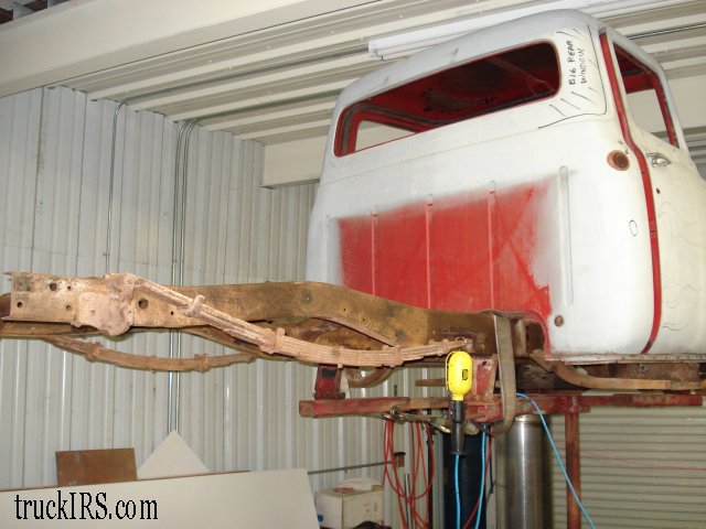
Our story begins with the bed removed from this 1956 Ford truck, the rear axle removed and all exhaust, brake lines, etc. moved out of the way. The rear leaf springs remain in place and will be removed in the first step.
Passenger’s side view of the truck’s frame after leaf spring removal. We cut the rivets holding the shackles with a torch, but other methods may be used to remove the springs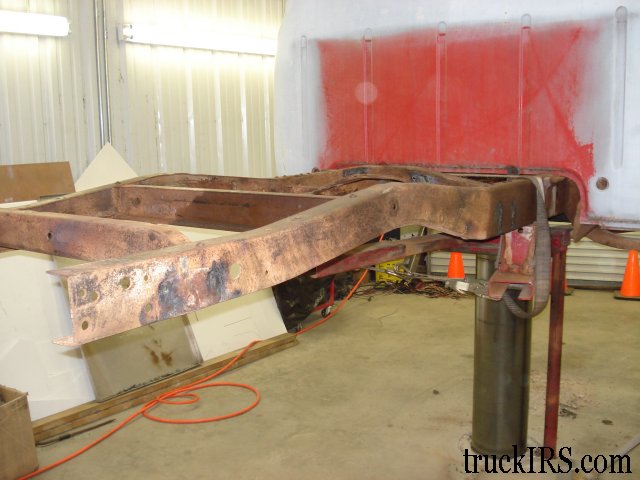
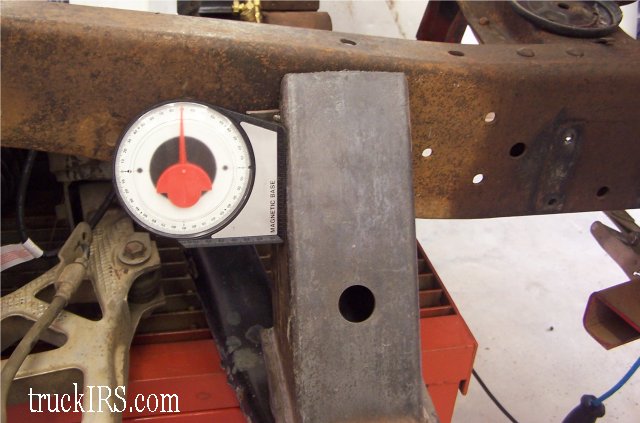
In addition to a level, angle finders come in very handy during this type of installation. The angle finders are inexpensive and help you to keep things level. the IRS assembly is positioned on a rolling cart and placed under the truck frame… as the frame is lowered via the lift.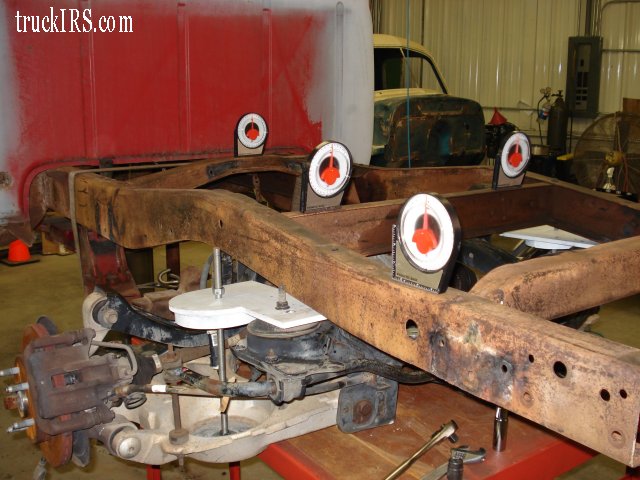
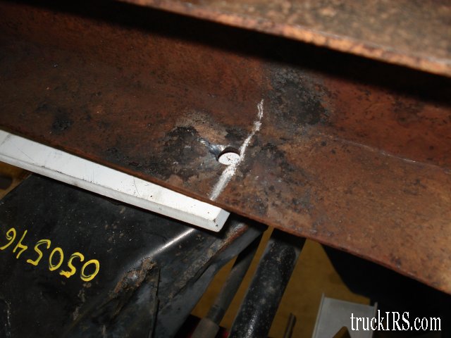
There is a small hole on the inside of the frame ( approximately 1/2″ diameter). This hole is located on the lower, flat surface of the frame on both the passenger’s and the driver’s side. This hole was previously used to mount a spare tire crossmember. This crossmember was not structurally integral to the frame and can be removed. The chalk line shown in the photo is made tangent to the rear edge of the this hole. Another verification of the location of this chalk line – it is 22 5/16″ from the rear of the truck’s frame.
The measurements above are for the particular truck shown in the install sequence. Ford changed the mounting holes over the years – so to be sure of where you make the vertical line and subsequent cut, measure 14 1/2″ behind the axle centerline.
Following the chalk line from the inside of the frame… continue the line along the lower ege of the frame. Draw a line from the lower edge of the frame upward 1 3/4″ The next step is to draw a horizontal line along the outer edge of the frame… toward the truck’s cab.
The reason we chose 1 3/4″ is that makes a nice horizontal mounting surface for the rear mount. Ford changed the frame profile over the years – some were more level, other frames provide more clearance above the rear axle. Regardless of the profile of the frame, the purpose of the vertical line is to provide a mounting surface for the rear mount. Make sure to use a level and a steel straight edge to draw this line.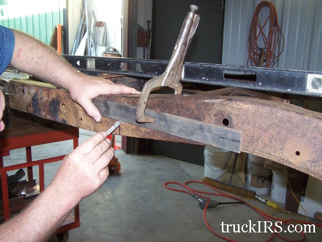
Clamp the steel straight edge in place along the side of the truck’s frame to be assured of a straight cut.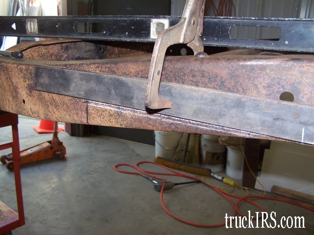
Here is an action photo of the frame modification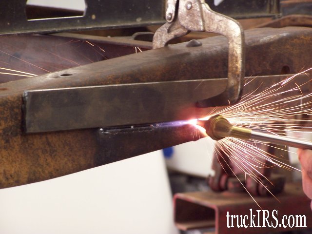
Notice that the cut line extends on either side ( fore and aft ) of the crossmember… This view shows the inside of the truck’s frame. The crossmember shown in the photo originally located the rear, upper shock mounts.
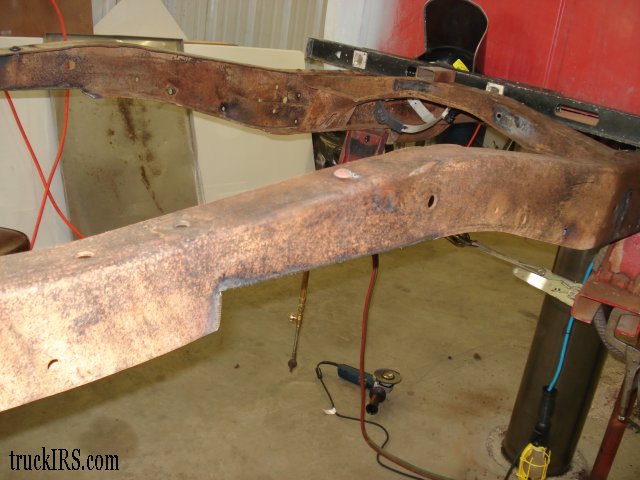
Once the driver’s and passenger’s side cuts are complete, remove the entire assembly – including the original crossmember.
Once the crossmember is removed, the frame rail appears as shown here.
Now that the frame has been modified, mate the IRS assembly to the truck’s frame to verify fit.
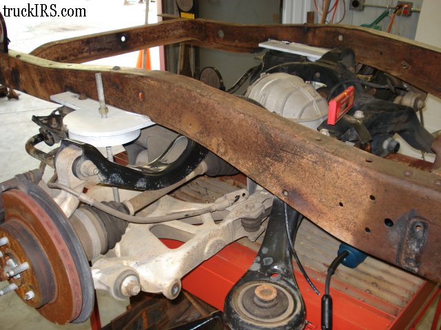
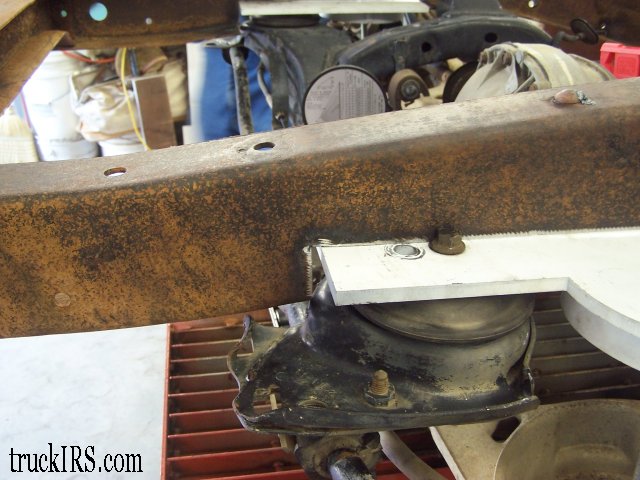
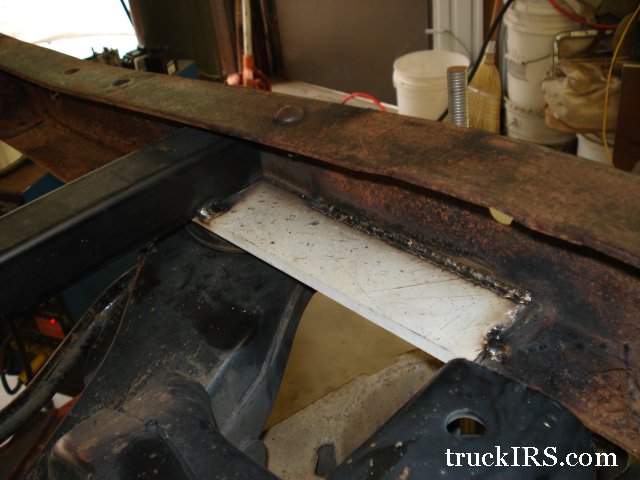
Here is a close-up view of the passenger’s side rear mount
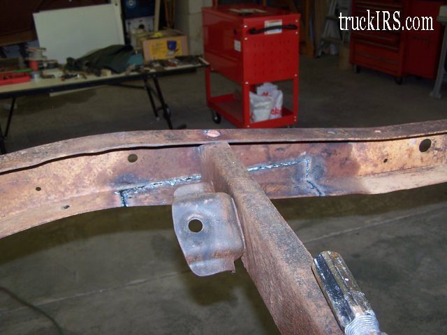
Since the original crossmember was removed to allow for the rear mounts to be welded in place, a new crossmember needs to be added. This rear crossmember is 2″ x 2″ square tubing. The original Ford frame rails are 34″ outside-to-outside. This new crossmember measures 33 11/16″ in length. Place this new crossmember on top of the rear mounting brackets. Center the ends of this crossmember about the rear mounting bolts… make sure it is level, clamp into place and weld to the mounting bracket as well as to the frame rails.
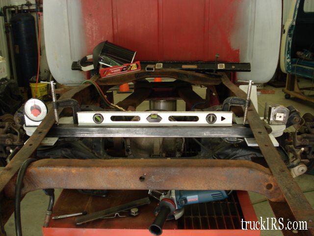
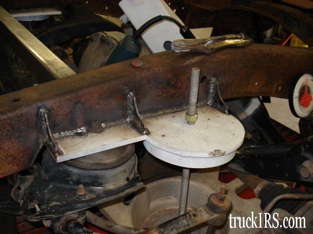
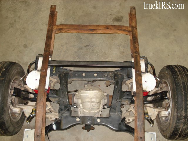
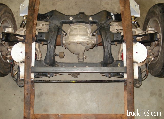
As viewed from the rear, verify that the rear mounts are level as well as the new crossmember. Once you verify that all is level, weld in place.
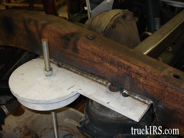
Here is a photo of the rear mount ( driver’s side ) finish welded. This view is from the outside of the frame rail.
This view of the driver’s side ( inside ) frame rail shows the finish weld along the entire seam between the rear mount and the frame rail.
Triangular gussets are welded between the rear mount and the outside of the frame rail.
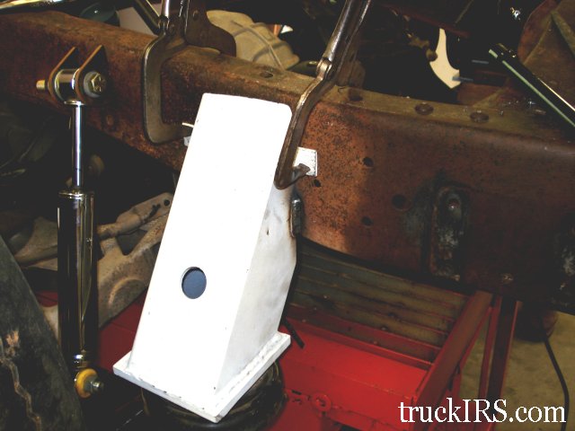
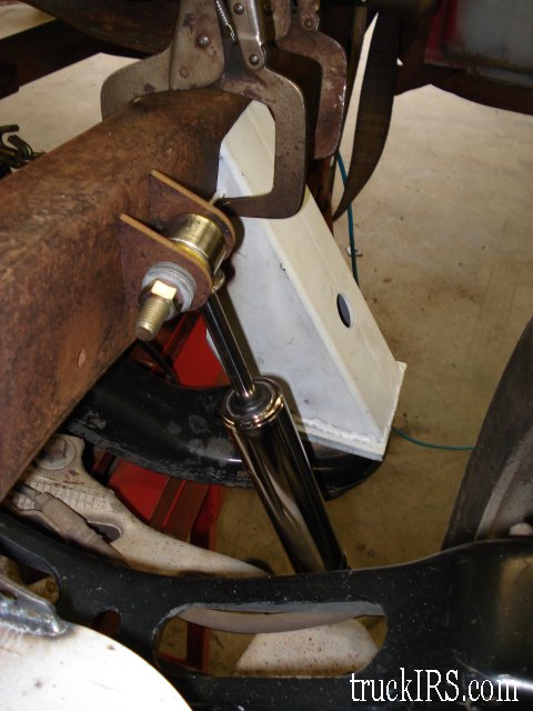
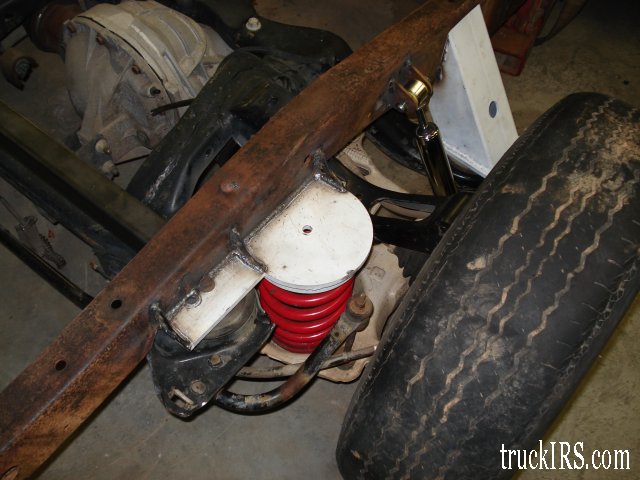
The rear mounts are welded in place… time to address the front mounts. Like before, make sure that the IRS assembly is level. The forward mounts no longer include the mounting tabs, as they are not necessary for fitment. You will also notice the shock located just behind the front mount on the passenger’s side
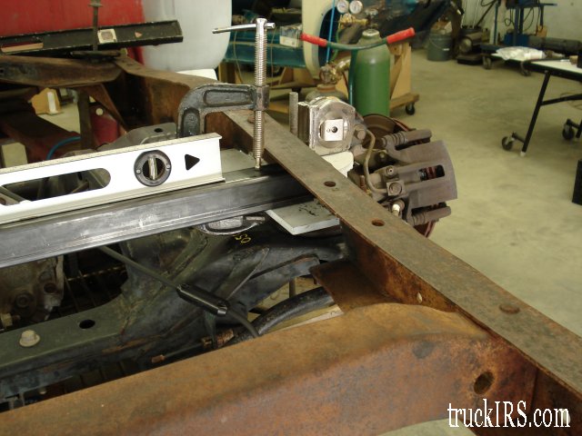
Just to reinforce the point – make sure the front mount is level prior to welding to the truck’s frame.
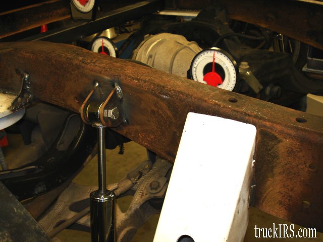
This view of the passenger’s side shows the front mount and upper shock mounts again. The location of the shock mount tabs is determined as follows: make sure the lower control arm’s inner mount and outer mounts are in line with each other. This is where the lower control arm wants to be for optimal performance. As a point of reference, the Lincoln Mark 8 Lower control arm air spring bucket to the underside of the rear mount is 10 1/4″
With the lower control arm properly positioned, attach the mounting tabs to the shock and extend the shock to its ride height position of 12″. This will allow proper compression and extension of the shock as the suspension moves through its range.
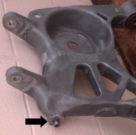
The factory shock uses 15mm or 16mm mounting bolts to mount the shock to the lower control arm. To use the recommended shocks – which use 1/2″ mounting nuts and bolts, I recommend drilling out the lower control arm’s shock mounting hole to 5/8″.
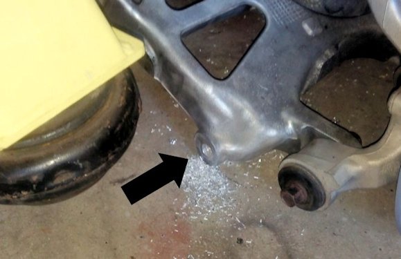
Then insert the 1.75″ long thin-walled tube (5/8″ OD / 1/2″ ID) into the lower control arm. These tubes are provided in the TruckIRS kit… note that the tube should be completely inserted… the tube is shown slightly out to indicate location.
The upper shock mounts are welded in place…
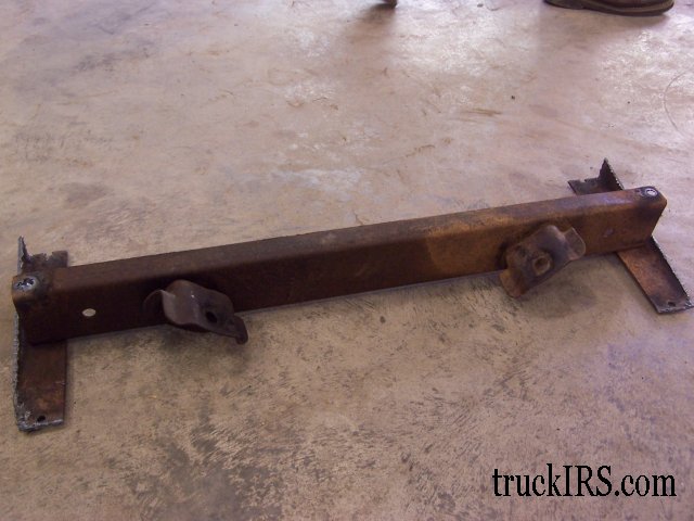
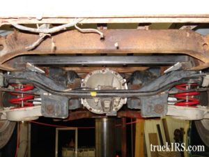
This view from the rear passenger’s side shows all four mounts welded in place, the upper shock mounts and crossmember are also welded.
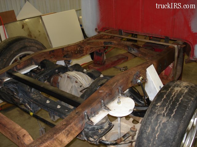
The factory Ford Thunderbird coil springs ( painted red for better contrast) are installed between the lower control arms and rear mounts.
This view from the top shows the IRS assembly… nice and clean install
… and another view looking down onto the IRS assembly… ready for the Bed to be lowered onto it.
This view of the passenger’s side shows the wheel / tire properly positioned in the fenders.
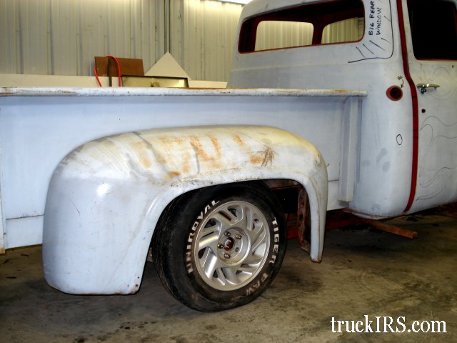
Another view showing the factory Ford Thunderbird wheels / tires fitting nicely in the fenderwell.
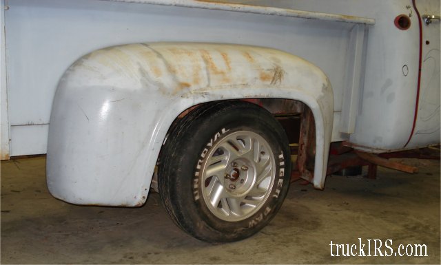
Viewed from the passenger’s side door looking rearward. This fender-level view shows the tires tucked neatly in the rear fenders.
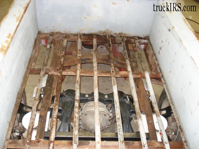
This bed viewed from the top with no wood installed allows an excellent view of the IRS
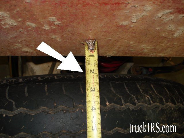
Removing the rear fender reveals the clearance between the outside of the bed and the tire.
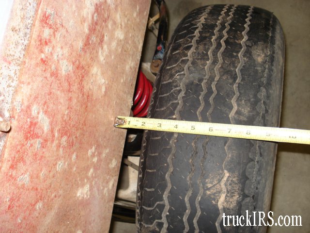
The factory Ford Thunderbird wheels / tires clear the outside of the bed by about 2 inches.
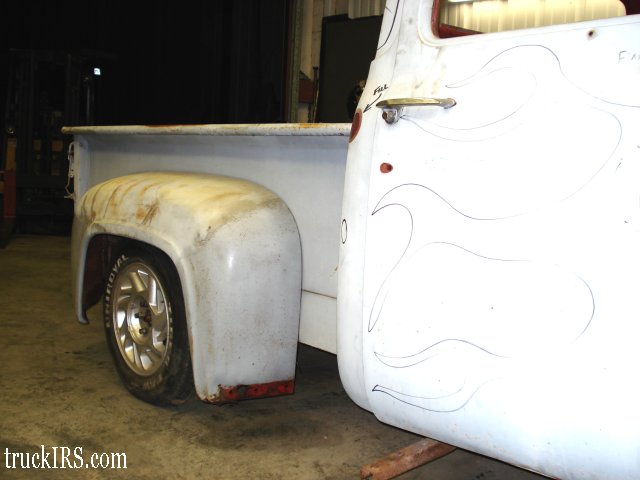
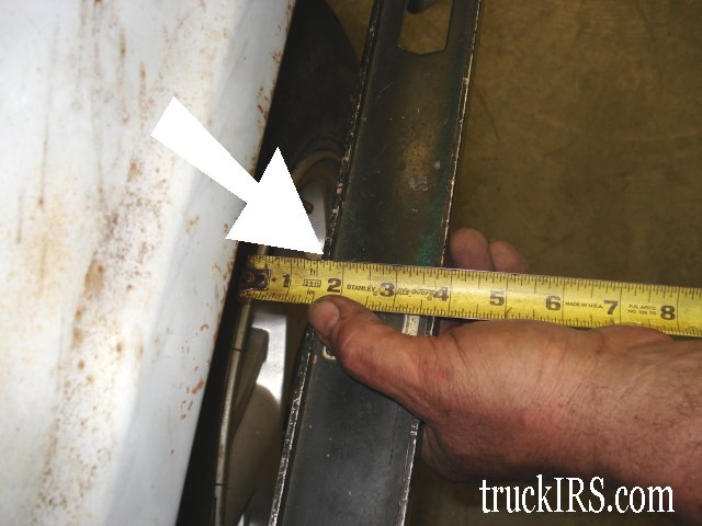
With the rear fenders back on the truck, a straight edge is placed on the outside lip of the rear fender.
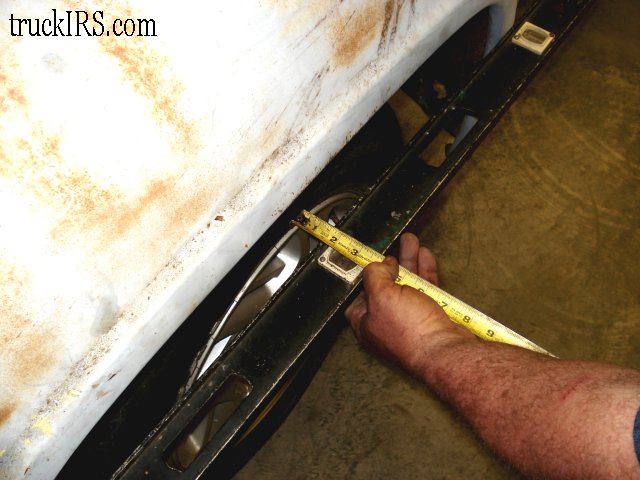
There is about 1 1/2 inches of clearance from the outside edge of the tire to the outer lip of the fender.
With the truck back up on the lift and the suspension supported at ride height, notice there are no clearance issues… no interference between the IRS assembly and the truck’s frame… and adequate spacing for exhaust pipes…

THE END… The rear end anyway!
Front Suspension
Rear Suspension
Team321 Customer Map